PotWatch / Components

Components

Nothing exotic and nothing proprietary. Every part here is a standard hobby-electronics module available from any of the usual suppliers, and the whole set comes to roughly EUR 25.

Shopping list

What to buy.

Part
What to look for
Photo
ESP32-C3 Super Mini
The microcontroller. Thumbnail-sized, a couple of euro, and it flashes over USB-C with no separate programmer.
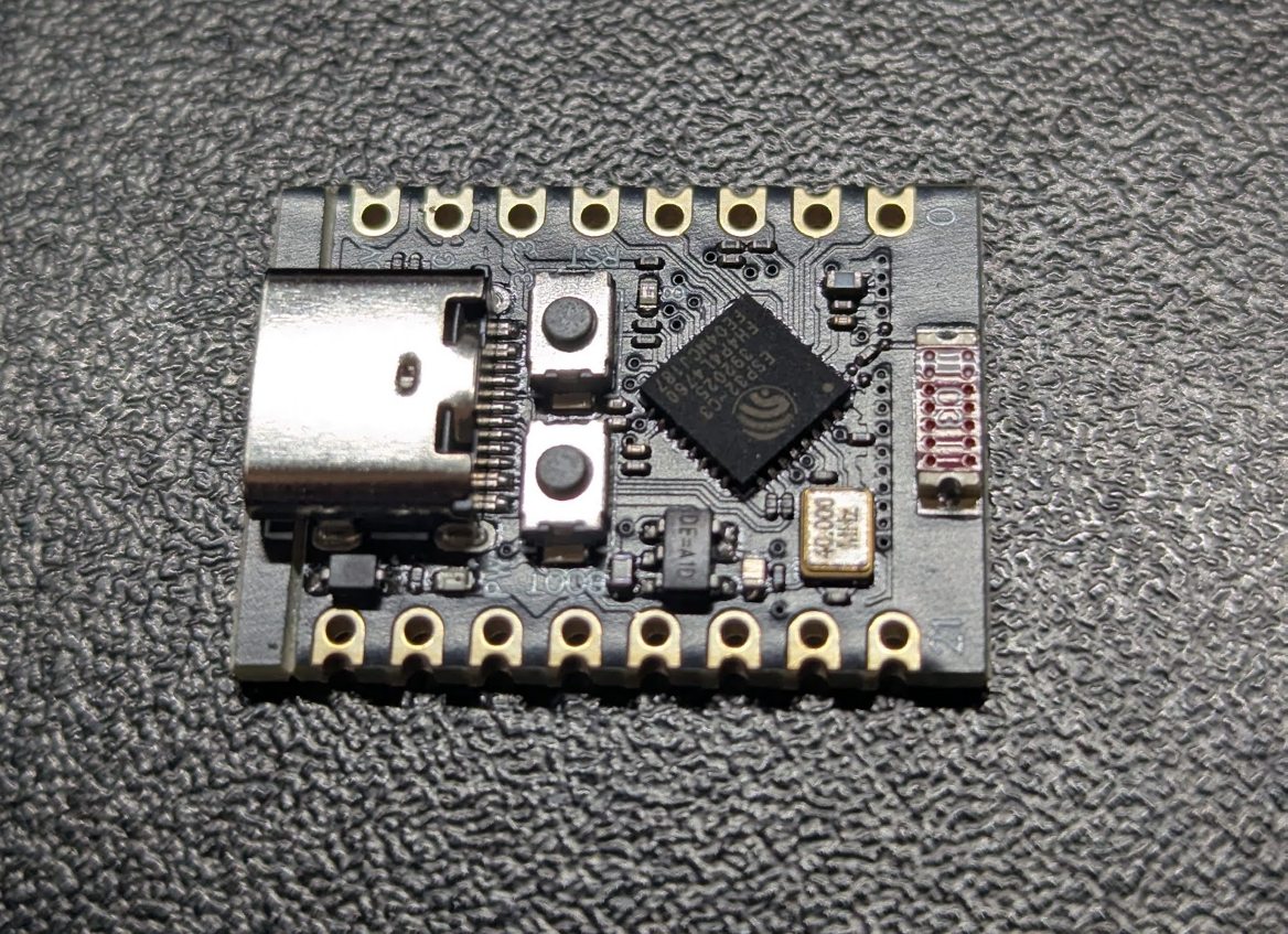
ESP32-C3 Super Mini board: a small black PCB with a USB-C socket, the ESP32-C3 chip and two rows of castellated pin pads
DS18B20 sensor
Buy the waterproof probe version — a sealed metal tip on a long lead, which is what slides inside the thermowell. The bare three-legged chip will not do.
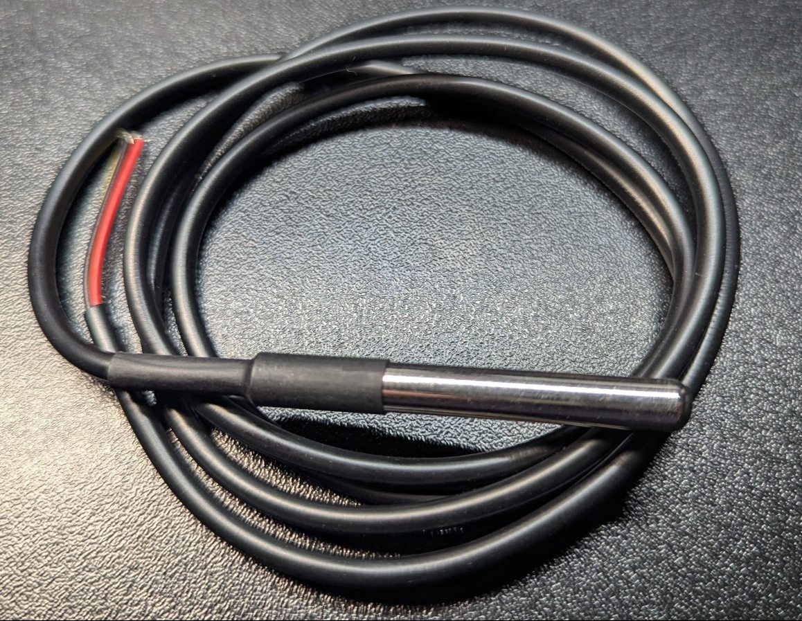
DS18B20 waterproof probe: a stainless steel tip on a coiled black cable with three bare wire ends
Stainless steel thermowell
A ready-made closed-end well with a threaded hex fitting and a cable gland that seals around the sensor lead. Food-grade stainless. Cut to suit your own pot — see the assembly page.
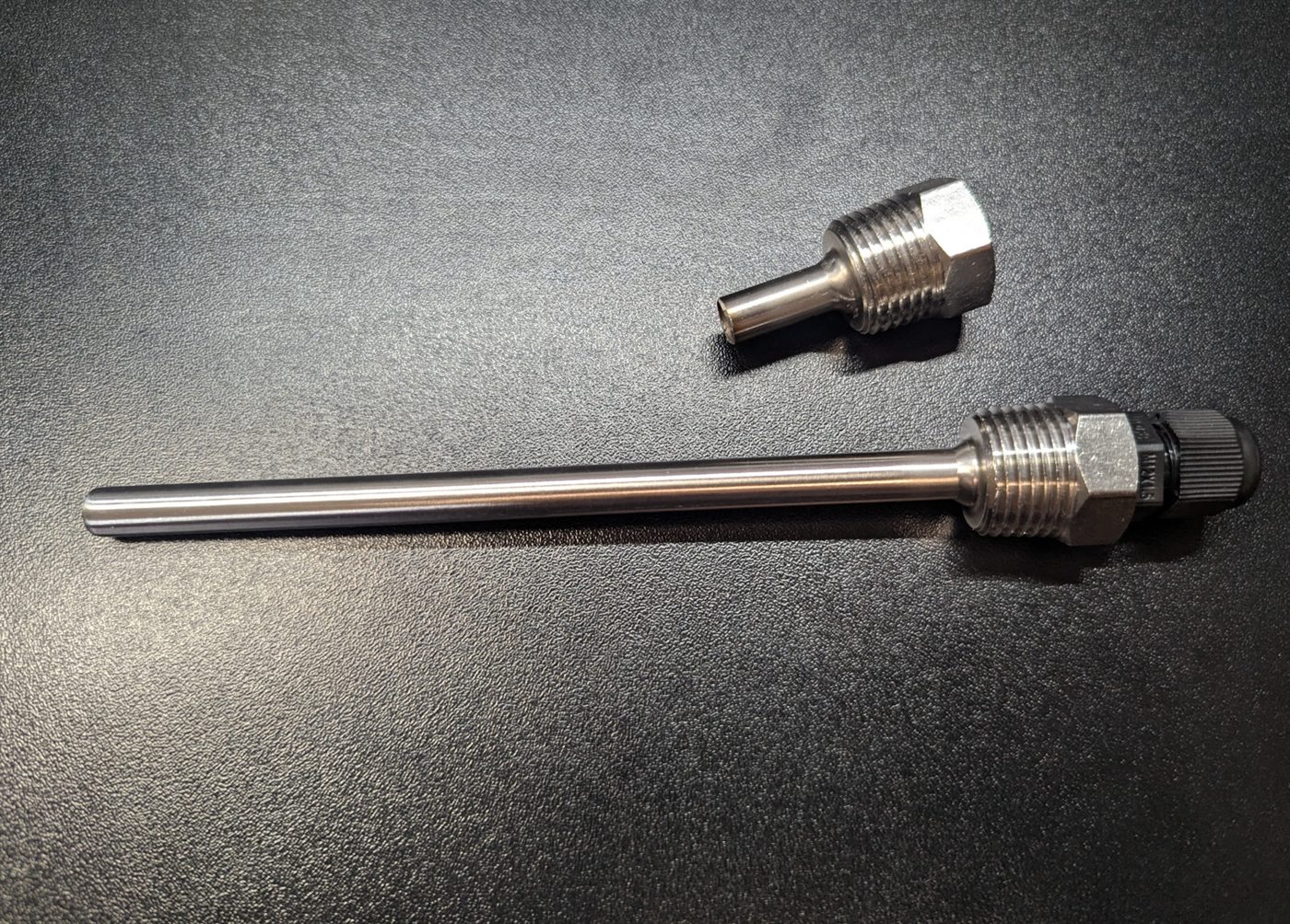
Stainless steel thermowell with a threaded hex fitting and a black cable gland, shown alongside a spare fitting
BMP280 barometer
The I²C version at address 0x76. Do not confuse it with the BME280 — that one also measures humidity, costs more and usually sits at 0x77. The purple boards look identical.

BMP280 barometric sensor on a small purple breakout board with a row of six pin holes
SSD1306 OLED, 128×64
A four-pin I²C module marked GND / VCC / SCL / SDA, address 0x3C. The 0.96 inch size is the one that fits the enclosure.
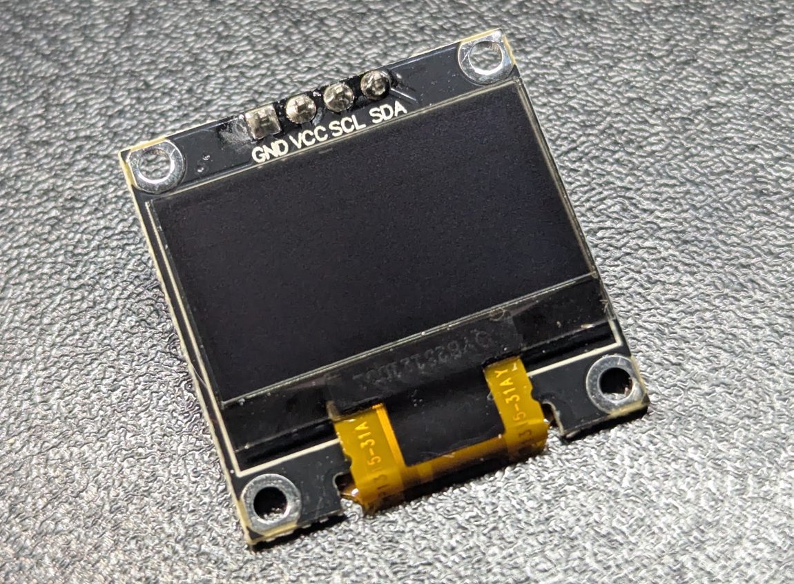
SSD1306 OLED display module with four pins labelled GND, VCC, SCL and SDA
Piezo buzzer
Passive, not active. An active buzzer has its own oscillator, knows exactly one note, and turns the alarm pattern into a single flat beep.
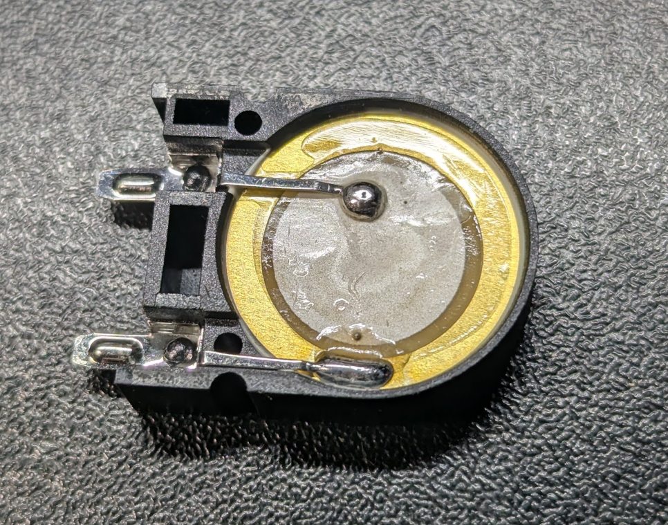
Passive piezo buzzer element with a brass disc and two solder tabs in a black holder
2 × push button
Panel-mount momentary buttons with a threaded barrel and nut, so they sit through the front shell. Two of them are the entire user interface. Colour is up to you — the prototype has black ones simply because that is what was ordered.
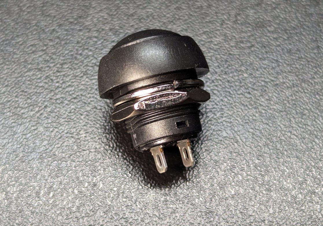
Round black panel-mount momentary push button with a threaded barrel and two solder tabs
4.7 kΩ resistor
The pull-up for the sensor data line. Costs nothing, and without it the probe returns nothing at all — a common first-build mistake.
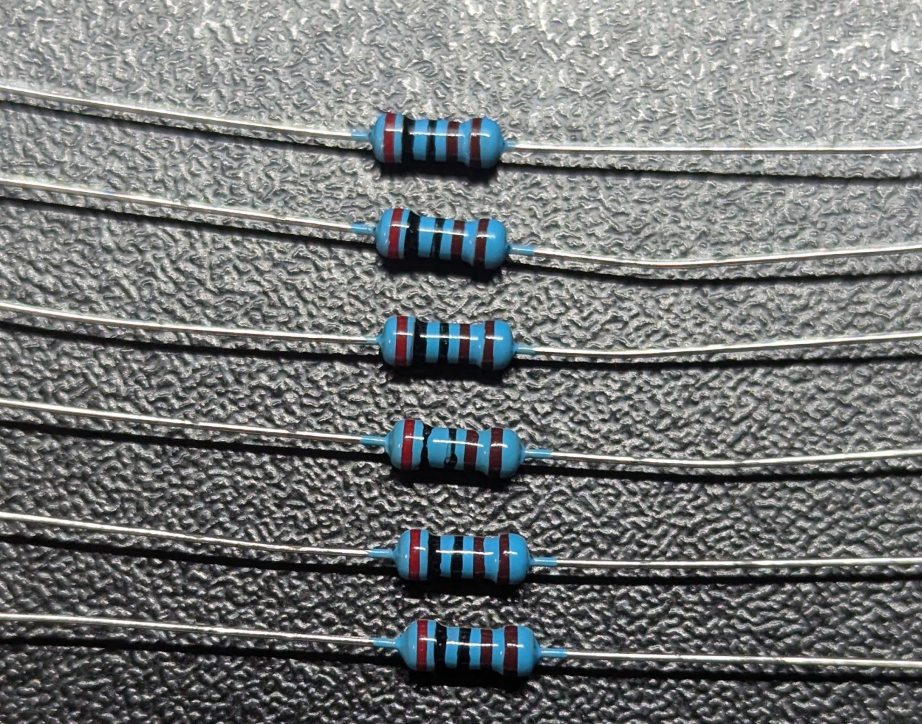
Several 4.7 kilohm metal film resistors with colour bands and long leads
Thermal paste
Ordinary CPU heatsink compound — the prototype uses HY510. The smallest syringe sold will build dozens of these.
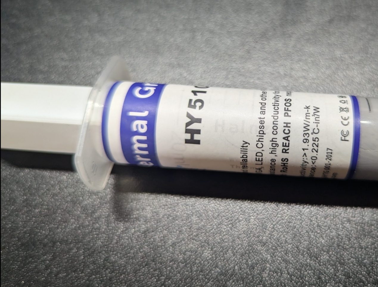
Syringe of HY510 thermal grease
Thin wire
To bond the thermowell to ground. Together with the paste, this is what stops induction hobs destroying the sensor.
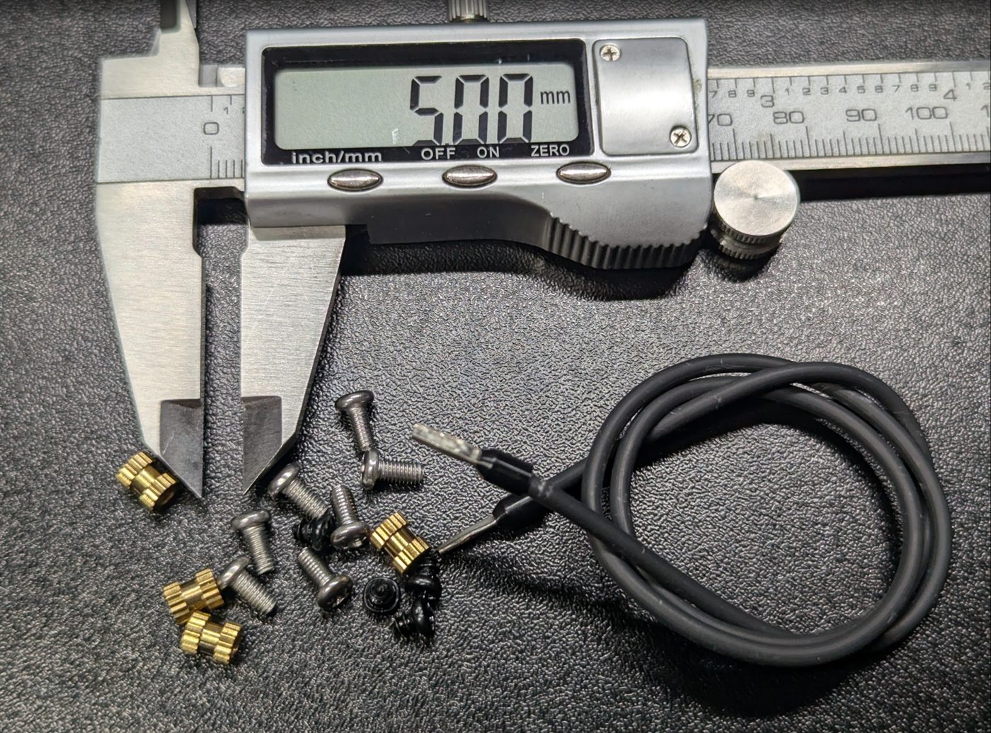
Fasteners laid out beside a digital caliper for scale: brass heat-set inserts, M3 screws, small black self-tapping screws for the display, and the black bonding wire with a terminal on one end
LiPo cell, 3.7 V
The prototype uses an 802060 pouch, 1000 mAh — flat, so it lies neatly inside the shell. Any similar cell with a protection circuit works; buy from a supplier you trust.
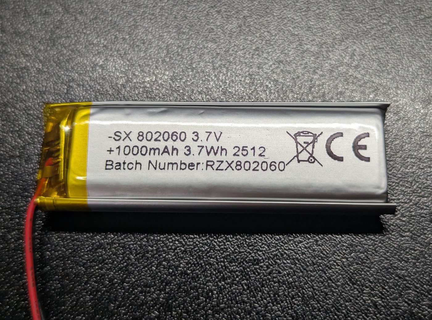
Flat lithium polymer pouch cell labelled 802060, 3.7 V, 1000 mAh, with red and black leads
TP4056 charger
The USB-C version with the battery protection circuit — look for the extra DW01 chip and dual MOSFET next to the output pads. The bare charging variant looks nearly identical and has no over-discharge protection.
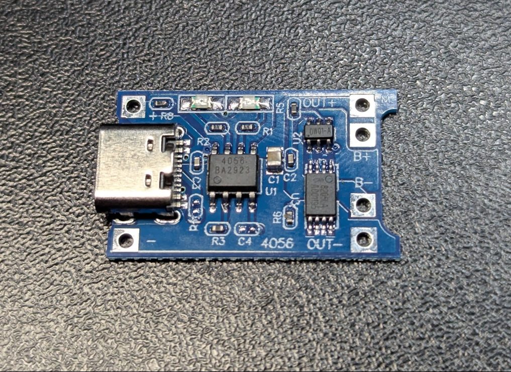
Blue TP4056 charging module with a USB-C socket, protection chip and B+ B- OUT+ OUT- pads
3.3 V step-down module
A small switching regulator that takes the cell voltage down to 3.3 V. Measured at 3.296 V on the prototype, so it holds regulation from a single cell even though the datasheet asks for a higher input — see the note below.
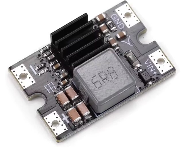
Small switching step-down regulator module with an inductor, heatsink fins and VIN and GND solder pads
Power switch
A small self-locking push switch — press for on, press again for off. Its mounting tabs screw into the shell. It breaks the 3.3 V line after the regulator.
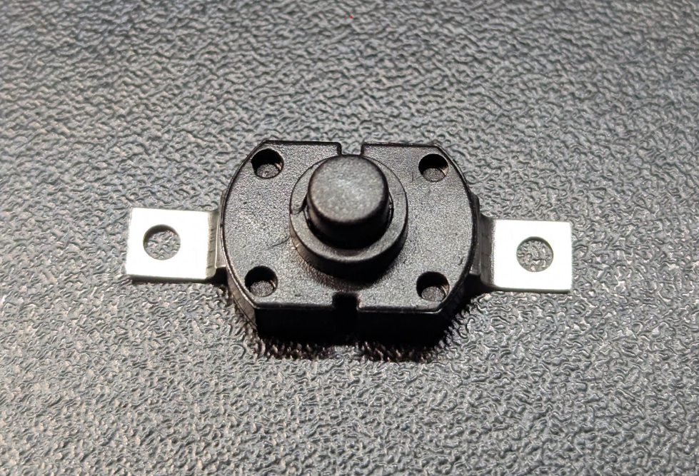
Small black self-locking push switch with two metal mounting tabs
Metal spring clip
The stainless clip that grips the pot rim, bought ready-made and screwed to the printed body. This is the weak point of the current design — see the assembly page.
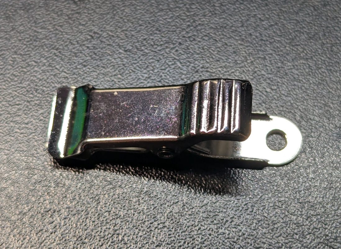
Stainless steel spring clip with a screw hole at one end
M3 screws, 6 mm — ×6
Four hold the cover onto the body, two fix the clip holders. On the prototype they cut their own thread straight into the plastic — the printed holes are 2.8 mm, deliberately undersized, so no nuts or inserts are needed. Prefer heat-set inserts? Open the holes out; the models are editable. The brass inserts in the photograph are there to show that option — the prototype does not use them.
Fasteners laid out beside a digital caliper for scale: brass heat-set inserts, M3 screws, small black self-tapping screws for the display, and the black bonding wire with a terminal on one end
Self-tappers, 2 mm — ×4
Retain the OLED behind the window. Thread length 4 mm at most — anything longer runs out of material. The holes in the cover are 1.8 mm.
Fasteners laid out beside a digital caliper for scale: brass heat-set inserts, M3 screws, small black self-tapping screws for the display, and the black bonding wire with a terminal on one end
Printed enclosure
Two printed shells plus the two clip holders. The prototype is fibre-reinforced ABS with an ASA cover, chosen because they stay rigid above a steaming pot where PLA would sag — see the assembly page.
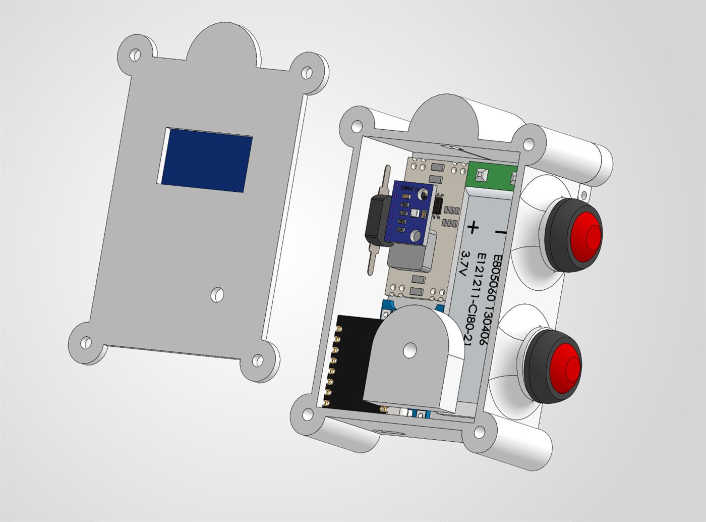
CAD render of the PotWatch enclosure opened up: the front shell with its display window beside the rear shell holding the board, regulator, battery, buzzer and the two buttons

// click any photograph to see it full size · the brass inserts in the fastener shot are an optional alternative, not part of the build

Choices that matter

Three parts where the wrong version will bite you.

The regulator runs below its stated input range — and that is fine

Getting 3.3 V out of a single lithium cell is harder than it looks. The cell starts at 4.2 V and falls to about 3.4 V before it is empty, so it spends its life barely above the voltage you are trying to produce.

The module on the prototype is a buck converter whose datasheet asks for a 6–25 V input and at least a volt more than the output. A single cell never meets that on paper — but measured on the assembled device the rail sits at 3.296 V, so in practice it regulates perfectly well. The vendor figure is simply conservative.

Worth knowing what happens at the end of the discharge: once the cell falls close to 3.3 V the converter can no longer step down, and the output follows the cell instead of holding steady. That is harmless here — the ESP32-C3 runs happily anywhere from 3.0 to 3.6 V — but it does mean the last part of the discharge curve is unregulated.

If you would rather not rely on a part running outside its specification, two alternatives are correct by the book: a genuine low-dropout linear regulator such as the HT7333 or MCP1700, which is the classic answer for one cell and draws microamps at rest; or a buck-boost converter, which holds 3.3 V across the entire discharge.

What will not work, however obvious it looks: the regulators everyone reaches for first are all wrong here. The LM2596 and MP1584 both need at least 4.5 V in — more than a full cell — so they simply never start. The AMS1117 needs over a volt of headroom and browns out at what looks like half charge. The LM2596 has a second problem too: it burns around 5 mA just idling, which would flatten a 1000 mAh cell in about a week with the device switched on and doing nothing at all.

So the test for a substitute is not whether it fits the shell. It is: does it work with an input below 4.2 V, and does it draw microamps rather than milliamps at rest?

The charger needs protection built in

TP4056 modules come in two flavours that look nearly identical. The one you want has a second chip and four output pads, and protects the cell against over-discharge and short circuits. The cheaper variant charges perfectly well and will happily let a lithium cell run flat enough to be damaged.

The buzzer must be passive

An active buzzer contains its own oscillator and only knows one note. The firmware drives the piezo with varying frequencies, so an active part will produce a single monotone beep — or nothing recognisable at all.

Budget

What it costs.

Prices vary enormously by supplier and quantity, so treat this as an order of magnitude rather than a quote. Buying from the slow, cheap end of the market:

~€10
microcontroller, sensors and display
~€10
battery, charging and power
~€5
tube, hardware, filament
~€25
all in, for one device

Most of these parts are sold in multiples, so a first build often costs a little more and the second one costs almost nothing.