PotWatch / Assembly

Assembly

An evening of work, most of it soldering. The only part that needs any mechanical care is the probe — and it is also the part that decides whether your device survives its first year on an induction hob.

Step 1

Print the enclosure.

The body is two printed shells that screw together around the electronics, with the clip that hangs the whole thing on the pot rim.

Choose the material with the steam in mind. This device spends its working life directly above a pot of boiling water, and PLA starts softening around 60 °C — uncomfortably close to what rising steam can deliver. The prototype is ABS and ASA; PETG is the compromise if your printer is open-frame. The full reasoning is a few paragraphs down.

Model
What it is
enclosure — STEP · STL
The main body — holds the board, battery, regulator and buzzer. 60.5 × 84 × 24 mm
cover — STEP · STL
The front shell, with the display window and button holes. 59 × 84 × 3 mm
holder1 — STEP · STL
Clip mount, part 1 — the two holders together carry the stainless spring clip. 59 × 15 × 5 mm
holder2 — STEP · STL
Clip mount, part 2. 35 × 15 × 5 mm

Every part comes in both formats. STL is the ready-to-slice mesh — take it if you just want to print the device as it is. STEP is the editable CAD source, so you can open it in FreeCAD, Fusion or SolidWorks and change anything you like.

STEP needs no conversion either: Bambu Studio, PrusaSlicer and OrcaSlicer all import it directly. Drop the file into the slicer exactly as you would an STL.

If you want to fix the clip, these are the two files

The clamping mechanism is the acknowledged weak point of this design, and conveniently it is also the most self-contained part of it: holder1 and holder2 are what hold the metal spring clip onto the body, and nothing else depends on their shape. You can redesign the whole mounting arrangement without touching the enclosure, the cover or any of the electronics.

If you come up with something that grips better and does not slacken, that is the single most valuable contribution this project could receive — and it costs you two files rather than a rebuild.

Part
Printed on the prototype in
Enclosure & clip holders
Fibre-reinforced ABS — green
Cover
ASA — blue

Standard slicer settings throughout. No tuned profile, no custom supports, nothing clever — the stock preset for each filament is what produced the parts in the photographs.

The material choice is the part that matters. This device spends its working life directly above a pot of boiling water, and ABS and ASA both stay rigid well past the temperature at which PLA begins to sag — PLA softens around 60 °C, which rising steam reaches without difficulty. ASA additionally shrugs off UV, which is why it suits the cover.

Both want an enclosed printer: they warp in a draught and their fumes are worth extracting. If you only have an open-frame machine, PETG is the sensible compromise — noticeably more heat-tolerant than PLA and far better behaved than ABS. Print PLA only if the device will never sit over a long boil.

One thing to check if you change material: the screw holes are printed undersized on purpose, at 2.8 mm and 1.8 mm, and different filaments shrink by different amounts. Test one hole before committing to the whole print.
Step 2

Prepare the probe.

The DS18B20 arrives as a sealed metal tip on a lead. That tip lives inside a stainless steel thermowell — a closed-end well with a threaded fitting and a cable gland — which gives the probe its length, its rigidity and, crucially, its protection.

  1. Cut the well to length. Thermowells are sold longer than you need. A rotary pipe cutter gives the cleanest result and does not fill the tube with swarf; a hacksaw works if you clear the filings afterwards. Long enough to reach well into the water, short enough not to touch the bottom of the pot.
  2. Deburr the cut. It leaves a sharp lip inside and out. Take it off with a file or a countersink bit — the inner burr will otherwise scrape the sensor lead as you push it through.
  3. Clean it thoroughly. Cutting oil, metal dust and fingerprints all end up in your food otherwise. Hot water, detergent and a final rinse.
  4. Fill the tip with thermal paste. A small amount of ordinary CPU heatsink compound in the closed end, then push the sensor in so the paste is squeezed around it with no air gap left.
  5. Bond the well to ground. Run a thin wire from the steel to the GND rail of the circuit. This is not optional if you cook on induction — see below.
  6. Tighten the cable gland around the sensor lead where it leaves the fitting, so steam and splashes cannot get inside.

Why the paste and the ground wire matter

Early prototypes destroyed DS18B20 sensors one after another. The cause was the induction hob: a bare semiconductor inside a metal tube, sitting next to a large alternating magnetic field. The steel sleeve added to protect the sensor was acting as an antenna, delivering the interference straight into it.

Grounding the tube turns it from an antenna into a shield wrapped around the sensor. The thermal paste was originally there to improve thermal contact — and it does, the probe responds noticeably faster with the air gap gone — but it also holds the sensor still inside that grounded enclosure.

Since this change the probe has survived repeated use on induction with no failures. That is several months of evidence rather than several years, so it is offered as "this fixed it for me" rather than "this is solved". If you build one and still lose a sensor, please get in touch.

Coming shortly: photographs of the probe assembly and the exact thermowell dimensions and thread size used on the prototype.
Step 3

Wire the electronics.

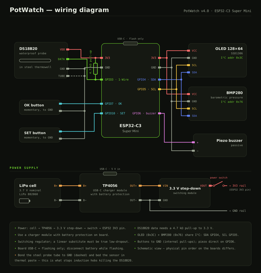
One I²C bus carries both the display and the barometer, the probe gets its own pin, and the two buttons switch straight to ground. That is the entire circuit.

ESP32-C3 pin
Goes to
GPIO3
DS18B20 data line — needs the 4.7 kΩ pull-up resistor to 3.3 V
GPIO4
I²C SDA — shared by the OLED (0x3C) and the BMP280 (0x76)
GPIO5
I²C SCL — the same two devices
GPIO6
Piezo buzzer, driven directly — no transistor needed
GPIO7
OK button, switching to GND (internal pull-up enabled in firmware)
GPIO10
SET button, switching to GND
3V3 / GND
Power rails for probe, display and barometer
GND
Also bonded to the stainless probe tube — see step 2
PotWatch wiring diagram: DS18B20 probe on GPIO3 with a 4.7 kilohm pull-up, SSD1306 OLED and BMP280 sharing the I2C bus on GPIO4 and GPIO5, piezo buzzer on GPIO6, OK and SET buttons on GPIO7 and GPIO10, plus the power chain of Li-ion cell, TP4056 USB-C charger, 3.3 V switching step-down module and power switch
fig. 1 — full hookup & power schematic, ESP32-C3 Super Mini download SVG ↓
Step 4

Build the power chain.

Four parts in a row: cell → TP4056 charger → 3.3 V step-down module → switch → the board's 3V3 pin. No mains voltage anywhere in the device.

Put the switch after the regulator rather than before the charger. That way the battery still charges while the device is switched off.

The USB-C socket on the ESP32 board itself is used for flashing only. Disconnect the battery before you plug it in.

A note on the regulator

The buck module used here has a datasheet asking for a 6–25 V input and at least a volt above the output, which a single cell never provides on paper. In practice it regulates fine — the assembled prototype measures 3.296 V on the 3V3 rail — so the vendor figure is conservative rather than binding.

At the very end of the discharge, once the cell approaches 3.3 V, the converter runs out of headroom and the output follows the cell down instead of holding. Harmless, since the ESP32-C3 is happy anywhere from 3.0 to 3.6 V, but worth knowing. If you prefer a part used strictly within specification, an HT7333 or MCP1700 low-dropout linear regulator is the textbook answer for a single cell, and a buck-boost module holds 3.3 V the whole way down.

Do not reach for an LM2596, MP1584 or AMS1117 — the usual first answers to "which regulator?" all fail here. The first two need 4.5 V or more at the input, which a full cell cannot give, and the LM2596 idles at around 5 mA on top of that. The components page has the reasoning.

Step 5

Fit it into the shell.

The display and the two panel-mount buttons sit in the front shell, behind the window and the button holes. The microcontroller, charger, regulator and battery go into the rear shell, and the probe lead leaves through the thermowell mount. The two halves close on M3 screws.

The stainless spring clip — a bought part, not a printed one — is sandwiched by the two printed holders and screws onto the body. That is what actually grips the pot rim.

Fastener
Where it goes
M3 × 6 mm — 4 off
Cover to body, one at each corner. Printed hole 2.8 mm
M3 × 6 mm — 2 off
Clip holders, and the spring clip through them. Printed hole 2.8 mm
2 mm self-tapper — 4 off
Display to the cover. Thread 4 mm at most. Printed hole 1.8 mm

The holes are printed deliberately undersized — 2.8 mm for the M3s and 1.8 mm for the display screws — so a screw cuts its own thread in the plastic as it goes in. That is how the prototype is put together, and it needs no nuts or inserts at all. Drive them gently the first time and do not overtighten; plastic threads strip far more easily than they cut.

None of this is prescriptive. Everyone has their own box of screws. If you would rather use heat-set inserts (there are some in the fastener photograph on the components page, shown purely as an example), or bolts and nuts, open the holes out to suit — the models are STEP, so changing a hole diameter is a two-minute edit. Inserts are the more durable choice if you expect to open the case often.

One dimension worth keeping: display screws with more than 4 mm of thread run out of material behind the window.

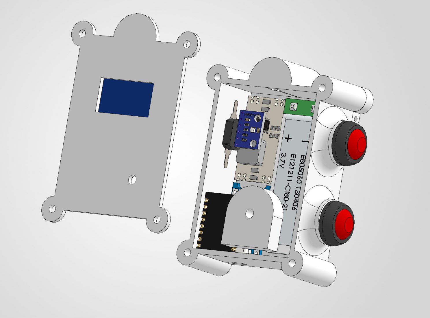
Exploded CAD view of PotWatch: the front shell with the display window on the left, and the rear shell on the right containing the ESP32 board, the step-down regulator, the flat LiPo cell, the piezo buzzer and the two panel-mount buttons
fig. 2 — how everything sits inside the two shells. Buttons are red in the render and black on the prototype; the colour is arbitrary

The layout is dense but not fiddly. The flat cell takes the whole right-hand side, the ESP32 board and the regulator stack along the middle, and the piezo sits at the bottom where the printed body has a recess for it. The buttons pass through the side wall on their threaded barrels.

Coming shortly: photographs of a real assembly at this stage, and the order in which the parts go in most easily.
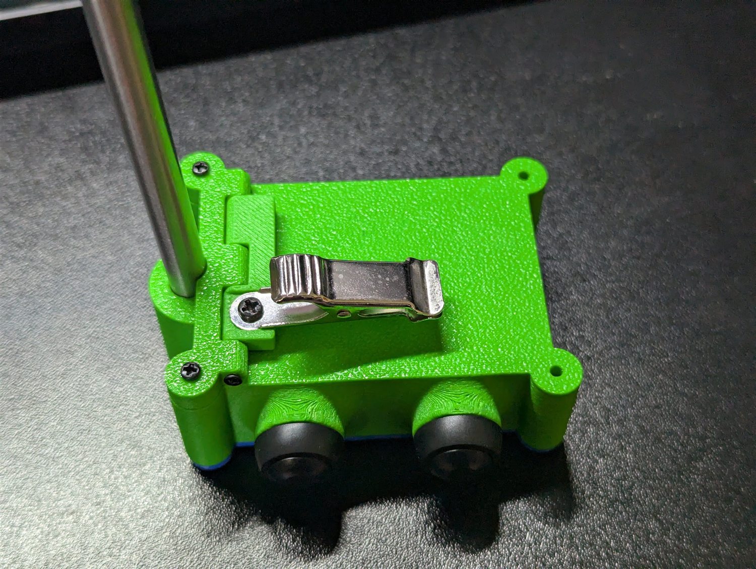
Close-up of the stainless spring clip screwed between the two printed holders on the green body, with the probe passing through alongside
fig. 3 — the spring clip sandwiched between holder1 and holder2

The clip is the weakest part of the current design

It holds the device on the pot rim only when its screws are done up firmly, and the tension slackens over time. Once slack it can tip, lifting the probe out of the liquid and into the air — where the device will faithfully report that your water is cold and wait forever.

A better clamp is being designed. Until then, check the probe is properly submerged before walking away, and re-tighten the screws from time to time. If you design a better clamp, that is the single most useful contribution anyone could make to this project.

It lives next to boiling water

This is a battery device with no mains connection, but it still combines a lithium cell, a hot pan and steam. Use the protected charger module, keep the cell away from the hot side, and do not leave a first build unattended.

Yours to build, change and share — here is how to credit it

The models, diagrams, photographs and this documentation are CC BY-SA 4.0. Most people who fail to attribute something are not stealing it; they just do not know what to write. So here is the line — put it in your description, your README, a caption, wherever it fits:

PotWatch by Ilia Kuzmin — https://potwatch.net
Licensed CC BY-SA 4.0. Modified from the original.

Drop the second sentence if you changed nothing. That is the whole obligation: name the author, link back, say that you changed it, and keep your version under the same licence.

The firmware is GPL v3, which asks for something different and rather lighter. It does not require you to advertise anyone — only to leave the copyright notice in the source, mark what you changed, release your version under GPL v3 as well, and give the source to anyone you hand a device to. Selling hardware that runs it is entirely allowed.

And an honest limit: copyright covers these files, not the idea. If you look at this thing and draw your own from scratch, you owe nothing at all — go ahead, and tell me how it turned out.